10 Tips for Choosing the Right Hydraulic Motor Control Valve?
Selecting the right Hydraulic Motor Control Valve can determine whether a machine runs smoothly or struggles under load. A valve may look ideal on paper, yet behave poorly in a dusty workshop or during cold starts. Real equipment exposes weaknesses quickly.
This guide presents ten practical tips based on hydraulic system design, maintenance experience, and manufacturer data. It examines flow capacity, pressure ratings, motor compatibility, control response, leakage, contamination tolerance, and installation requirements. These details matter when a motor drives a conveyor, winch, auger, or tracked vehicle. Small mismatches can cause heat, noise, unstable speed, or premature component wear.
Check the numbers carefully.
A reliable selection process also considers service conditions and future maintenance. Confirm the valve’s rated flow against the motor’s actual demand, not only the pump’s maximum output. Review relief settings, return-line pressure, oil cleanliness, seal materials, and connection standards. A respected supplier should provide clear performance curves, test information, and technical support. Still, documentation is not the whole story. Field feedback, inspection records, and a controlled trial can reveal problems that catalogues miss.
Some choices remain uncertain.
For that reason, the discussion also highlights common selection mistakes and practical checks before purchase. No single valve suits every hydraulic circuit. The best option balances performance, safety, durability, availability, and total operating cost. Readers should verify final specifications with qualified hydraulic professionals and the equipment manufacturer, especially when pressure, load, or environmental conditions change.
Define the Hydraulic Motor’s Operating Requirements
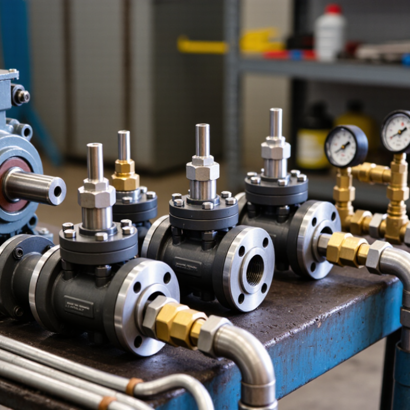
Before selecting a hydraulic motor control valve, define the motor’s actual operating requirements. Record the required speed range, torque, direction changes, and duty cycle. Measure pressure and flow during startup, peak load, and normal running. Do not rely only on catalog ratings. Real systems often behave differently.
Tip 1
Match the valve to both continuous and peak conditions. A motor lifting a 500-kilogram load needs different control behavior from a conveyor running at steady speed. Note the motor displacement, maximum pressure, available flow, and acceptable speed variation. Also check whether the circuit needs braking, load holding, or overload protection. These details affect valve selection.
Tip 2
Study the operating environment. Dust, cold starts, high oil temperature, and limited installation space can change performance. Specify the control signal, response time, port size, and mounting position. I have seen designs fail because the expected flow was calculated without considering hose losses. A spreadsheet may look precise, but field measurements deserve more trust. Recheck uncertain figures before approval. Small errors can cause heat, noise, or unstable motion.
Evaluate Control Precision, Response Speed, and Efficiency
Choosing the right hydraulic motor control valve starts with measurable control precision. Specify flow accuracy, pressure stability, and allowable hysteresis before comparing models. A valve that responds smoothly at 10% command may still drift under changing loads. In field testing, record shaft speed, outlet pressure, and temperature at several load points. Do not trust catalog claims alone. Tip 1: Test the valve with your actual oil viscosity and motor inertia. Small differences can become visible oscillations.
Response speed matters when a machine accelerates, reverses, or stops repeatedly. Measure command-to-motion delay with a pressure transducer and tachometer. A fast valve is not always better. Excessive gain can create hunting, noise, and mechanical stress. The International Energy Agency reports that electric motor systems consume about 53% of global electricity, making efficient control a significant engineering concern. Hydraulic losses still deserve close attention, especially during throttling. Tip 2: Compare pressure drop at normal flow, not only at rated flow. Tip 3: Check response at cold startup.
Efficiency depends on the complete circuit. Select a valve that matches displacement, flow demand, relief settings, and duty cycle. The U.S. Department of Energy has estimated that motor-driven systems use roughly 70% of industrial electricity in the United States. That figure is not a hydraulic-specific measurement, but it shows why avoidable control losses matter. My practical mistake has been focusing on peak efficiency while ignoring partial-load behavior. Tip 4: Calculate wasted power as pressure drop multiplied by flow, then verify it during real production cycles.
Check Compatibility, Installation Needs, and Environmental Conditions
Choosing the right hydraulic motor control valve requires more than matching port size. Confirm the motor’s rated pressure, flow, displacement, and speed range. Check whether the valve supports proportional or on-off control. A field technician should also verify mounting dimensions and hose connections before ordering. Small mismatches create expensive delays.
Compatibility comes first. Review fluid type, seal material, filtration level, and operating temperature. ISO 4413 recommends controlling contamination and protecting hydraulic components from unsafe pressure conditions. ISO 4406 cleanliness codes help define filtration targets. Do not ignore them. The U.S. Department of Energy’s 2021 Motor Systems Market Assessment estimates that motor-driven equipment consumes about 23% of U.S. electricity. Efficient valve selection can reduce avoidable losses, though real savings depend on the complete circuit.
Installation conditions matter just as much. Measure available space, cable routing, vibration, noise, and service access. Outdoor systems may need protection from rain, dust, salt, or severe temperature changes. Choose feedback and control signals that match the existing controller. A valve rated for the right pressure can still fail in a hot, dirty enclosure. That is easy to overlook. I would also test the valve under peak load, not only normal operation. This approach may add inspection time, but it exposes weak assumptions before commissioning. Use the manufacturer’s technical data, ISO requirements, and documented site measurements instead of relying on appearance or price.
Compare Safety Features, Maintenance Demands, and Total Cost
10 Tips for Choosing the Right Hydraulic Motor Control Valve?
Compare Safety Features, Maintenance Demands, and Total Cost
Choosing a hydraulic motor control valve begins with the machine’s real operating conditions. Record pressure, flow, load changes, temperature, and cycle frequency before comparing specifications. Safety features deserve close attention, including overload relief, pressure limiting, emergency-stop compatibility, and controlled load holding. A valve should fail predictably when power or signal is lost. Safety comes first.
During field inspections, I look for accessible test ports, clear adjustment markings, replaceable seals, and contamination indicators. Small leaks matter. They can hide rising maintenance costs and create slippery work areas. Check whether technicians can service the valve without removing nearby pipes. Review filter requirements, recommended inspection intervals, and the availability of technical documentation. A diagnostic port may cost more initially, but it can reduce troubleshooting time.
Total cost includes more than the purchase price. Compare installation labor, energy losses, fluid consumption, spare parts, training, and expected downtime. A cheaper valve may require frequent adjustments or cause slower motor response. Conversely, an advanced valve may be unnecessary for a simple, stable circuit. I have seen teams over-specify equipment because the data sheet looked impressive. That choice was expensive. Use measured operating data, not assumptions, and ask a qualified technician to verify compatibility with the pump, actuator, fluid, and control system.
10 Tips for Choosing the Right Hydraulic Motor Control Valve
Comparison of safety features, maintenance demands, and total-cost efficiency
Relative engineering screening scores from 1 to 5. A higher score indicates stronger safety readiness, simpler maintenance, or better total-cost efficiency. Actual results depend on operating pressure, duty cycle, contamination control, installation quality, and required feedback accuracy.