Choosing the right Pump Control system affects more than how a pump starts and stops. It influences energy use, equipment life, pressure stability, and daily maintenance. A system suited to a clean-water booster may not work well with a slurry pump or a variable-demand process. The details matter.
Start with the pump’s duty point, flow range, and operating schedule. Compare those requirements with the pump curve and the control panel’s rated capacity. A variable-frequency drive can adjust motor speed when demand changes, while a pressure switch may suit a simpler, steady-duty application. Neither option is automatically better. Check sensor accuracy, motor compatibility, enclosure rating, and available fault protection. For example, a pressure sensor exposed to vibration or moisture may produce unreliable readings over time. Small details can become expensive problems.
Consider who will operate and service the system. Clear alarms, accessible wiring diagrams, and commonly available replacement parts can save time during a busy shift. Ask the pump manufacturer or a qualified controls professional to verify the design against site conditions and equipment specifications. Keep future changes in view, too: adding a pump or changing demand can alter control requirements. A perfect choice is rare. I have seen systems selected around purchase price alone, only for operators to struggle with frequent cycling and confusing alarms. That is a useful reminder: document the actual operating conditions before choosing, and revisit assumptions when they do not match what happens in the field.
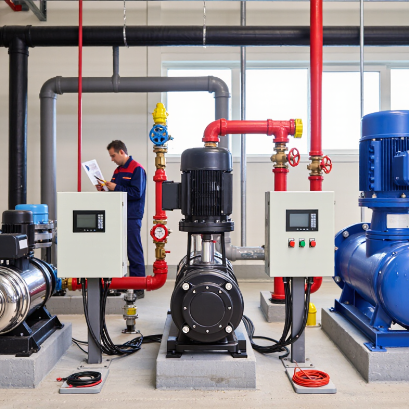
A pump control system should be selected around a verified duty point, not a list of controller features. Record the required flow rate and discharge pressure, then calculate total dynamic head at that flow. Include elevation changes, pipe friction, and equipment losses. Keep units consistent. Plot the resulting flow-and-head point on the pump curve for the actual impeller diameter and speed. Check efficiency, motor power, and the recommended operating range; a point near the curve’s best-efficiency region is usually preferable, but the real system may not behave neatly.
The U.S. Department of Energy’s Improving Pumping System Performance sourcebook reports that pumping systems can account for 25–50% of energy use in some industrial facility operations. This is not a universal figure, but it shows why mismatched controls can matter. For variable demand, compare expected operating points across the day, not only at peak flow. Confirm minimum flow, maximum head, suction conditions, and motor current against site measurements. Drawings can be outdated. I have seen a small difference in pipe routing shift the predicted duty point.
Tips: Keep the pump curve, measured flow, and head readings together. Mark normal, minimum, and peak demand on the curve before choosing a control strategy. If the points fall outside the suitable range, revisit the pump or system assumptions.
A pump control system should match the way demand changes through the day. When flow stays fairly constant, a fixed-speed pump can be a practical choice. It runs at one speed and starts or stops as pressure changes. Check how often it cycles; repeated starts can add wear and create pressure swings. Keep it simple, but verify the operating conditions.
Staged control suits systems with several pumps and demand that rises in clear steps. One pump can handle light use, while additional pumps start as flow increases. This can spread operating hours across the equipment. It also needs thoughtful sequencing: poorly chosen start and stop points may cause frequent switching. Watch the pressure readings during real demand, not just during a quiet test.
A variable-frequency drive adjusts motor speed as demand changes. It can help maintain steadier pressure in systems with frequent, gradual flow changes, such as a building with busy morning use and quiet afternoons. But a VFD is not automatically the best option; pump selection, minimum flow, sensor location, and setup all matter. Compare expected demand with the pump curve, then review energy use and cycling after installation. Field conditions may disagree with the original estimate, and that is worth revisiting.
| Selection Factor | Fixed-Speed Control | Staged Control | VFD Control |
|---|---|---|---|
| How it works | A pump runs at a constant motor speed. Flow is managed by starting or stopping the pump, or by using a valve or bypass where the system requires it. | Two or more pumps are switched on or off in sequence as demand changes. Pumps may be lead-lag rotated to balance operating hours. | A variable-frequency drive changes motor speed to adjust pump output. A controller commonly varies speed to maintain a pressure, flow, or level setpoint. |
| Demand matching | Limited. Output stays near the pump’s operating point while it is running; demand changes are typically handled by cycling or throttling. | Moderate. Capacity changes in discrete steps as pumps are added or stopped. | Continuous within the pump and motor’s permitted operating range, making it suitable for frequently changing demand. |
| Typical arrangement | One pump for a steady-duty process, or a pump operated by a pressure switch for a simple system. | Multiple pumps in parallel for applications with several recurring demand levels or a need for standby capacity. | One variable-speed pump, or a VFD-controlled lead pump with additional fixed-speed pumps for higher demand or backup. |
| Part-load energy considerations | Can use more energy than necessary when excess flow is controlled by throttling or bypassing. Suitability depends on the pump curve and system demand. | Can improve part-load operation by running only the number of pumps needed, provided the selected pumps operate efficiently at their loaded conditions. | Can reduce energy use when speed reduction meaningfully reduces required pump output. For centrifugal pumps, power may fall approximately with the cube of speed in suitable conditions; actual savings depend on system head, pump efficiency, and control settings. |
| Pressure or flow behavior | May produce pressure or flow variation as demand changes. A control valve can regulate the process but may add hydraulic losses. | Output changes in steps. Pressure can vary during pump transitions unless the system includes appropriate control and capacity is well matched. | Can maintain a configured setpoint more closely as demand varies, subject to sensor placement, tuning, pump limits, and system design. |
| Starting and cycling | Starts at full speed. Frequent starts can increase electrical and mechanical stress; switching frequency should be considered in pump and motor selection. | Can reduce frequent cycling of a single pump by sharing demand, but staging thresholds and minimum run times need proper setup. | Typically ramps motor speed during starting and adjusts output without repeatedly switching the motor on and off, within drive and motor limits. |
| Control and maintenance | Usually the simplest option to configure and maintain. Protection, isolation, and any required pressure or level controls are still needed. | Requires sequencing logic, pump status monitoring, and suitable staging and rotation settings. | Requires drive setup, compatible motor and electrical installation, suitable sensors, and attention to heat, electrical noise, and maintenance requirements. |
| Relative installation complexity | Low for a basic single-pump arrangement. | Moderate; increases with the number of pumps and the control logic required. | Moderate to high, depending on drive location, motor compatibility, sensors, electrical requirements, and control integration. |
| Often a good fit when | Demand is steady, the pump operates near its design point, and simple operation is a priority. | Demand has a few predictable levels, several pumps are available, or standby capacity is important. | Demand varies frequently and the pump can operate efficiently over the required speed range. |
| Check before selecting | Confirm that fixed output will not cause excessive throttling, bypass flow, short cycling, or operation outside the preferred pump range. | Check pump sizing, the efficiency of each operating combination, transition behavior, and how standby capacity will be provided. | Check minimum and maximum speed limits, minimum flow and cooling requirements, static head, motor suitability, and whether the drive can meet the required duty point. |
Selection note: These are general comparisons, not guaranteed performance outcomes. Confirm pump curves, system characteristics, motor limits, and control requirements with a qualified designer.
How to Choose the Right Pump Control System
Pump affinity laws help estimate what a speed change will do. With the same pump and impeller diameter, flow varies roughly with speed, head with speed squared, and power with speed cubed. At 90% speed, the estimates are 90% flow, 81% head, and about 73% power. That matters. A variable-speed control system can reduce energy use when demand changes, but the estimates are not guarantees. Actual results depend on the pump and system.
Check the duty point before choosing a controller. A pressure gauge, flow meter, and motor data can reveal whether the pump runs beyond its real demand. Also consider static head: lowering speed may reduce available head until the pump can no longer serve the system. In field checks, a small speed adjustment can expose noisy valves or an oversized pump. It is easy to blame the controller instead. I have seen that assumption waste time.
Tips: Record flow, pressure, and power at several speeds. Change speed gradually, then confirm the new operating point with measurements. Keep a margin for peak demand, and verify motor cooling at lower speeds. Affinity laws are a useful starting point, not a substitute for commissioning data.
How to Choose the Right Pump Control System
Choosing a pump control system means checking more than the control panel’s voltage. IEC 60034 and NEMA MG 1 provide motor requirements and performance guidance, but they are not interchangeable labels. Confirm the standard and edition cited on the motor documents. Then compare the nameplate voltage, frequency, rated speed, and duty with the site supply and control equipment. Small mismatches matter.
Check the motor’s starting current against the controller’s capacity, especially with direct-on-line starting. For a variable-frequency drive, verify that the motor is suitable for speed control and that its insulation, cooling, and operating range fit the planned speed profile. A pump running slowly may receive less cooling from its own fan. That detail is easy to overlook. Also check the enclosure and ambient-temperature ratings against the actual installation, not just the equipment schedule.
A standards reference alone does not prove that a motor and controller will work well together. Review the manufacturer’s motor data, controller documentation, and any stated limits for cable length or switching frequency. Ask the supplier to clarify gaps in writing. A tidy spreadsheet can still miss a real operating condition, such as frequent starts or a hot, poorly ventilated pump room. Do not assume. Verify the complete motor-control combination before purchase.
Choosing a pump control system starts with understanding the motor’s role in the plant’s energy use. The U.S. Department of Energy estimates that motors consume about 69% of U.S. industrial electricity. That figure makes motor-driven equipment worth a careful look, but it does not mean every pump offers the same savings opportunity. A pump running against a throttled valve may behave differently from one serving changing production demand. Check actual flow, pressure, operating hours, and motor load before comparing controls.
A variable-frequency drive can adjust pump speed to match demand, potentially avoiding needless flow and energy use. But it is not automatically the right choice. Consider the pump’s operating range, minimum flow needs, control response, and compatibility with existing equipment. A shift in speed can affect pressure and process stability. Small details matter. Review utility bills and collect operating data over representative shifts; a single reading can be misleading. Then compare the expected energy impact with installation and maintenance needs. I would be cautious about promises based on ideal conditions alone. Real systems are messy, and measured results may differ from projections. No shortcut. A sound decision uses site data, clear operating requirements, and a documented commissioning check.
Motor-driven systems account for an estimated 69% of electricity use in U.S. manufacturing. Since pumps are motor-driven loads, choosing an appropriately sized pump and control strategy can help manage electricity use; actual savings depend on the system and operating conditions.
Source: U.S. Department of Energy estimate. The 31% represents electricity used for other manufacturing purposes.
Hi! Simply click below and type your query.
Our experts will reply you very soon.