In a process plant, a control signal may call for a valve to open halfway, yet the valve does not always move there smoothly. Friction in the stem, changing air pressure, or load on the actuator can leave the actual position short of the target. A Valve Positioner helps close that gap. It compares the requested position with feedback from the valve, then adjusts actuator pressure to bring the valve closer to the setpoint. Small device. Big effect.
This article explains why a positioner is used, how it supports more accurate control, and where its limits matter. In the field, the difference can show up as steadier flow through a pipe or less hunting in a control loop. Some models also provide diagnostics, but available features vary. A positioner cannot correct every problem: a sticking valve, poor sizing, or incorrect tuning may still require attention. It is tempting to treat the instrument as a simple add-on. That can be misleading. Its performance depends on the valve, actuator, signal, and installation working together. Understanding that relationship helps engineers and technicians choose, commission, and maintain equipment with greater confidence.
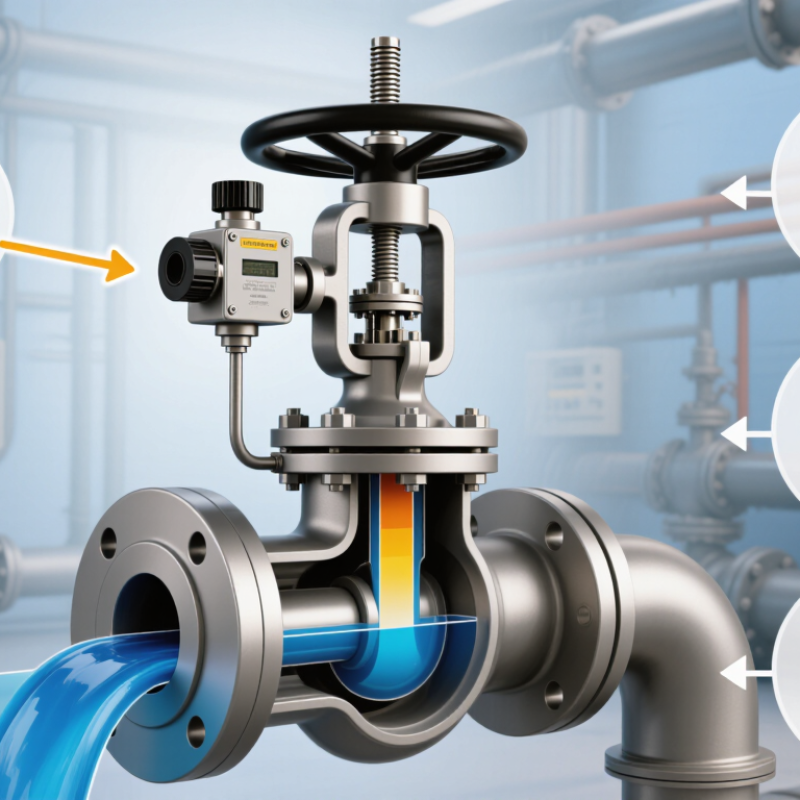
A valve positioner is the feedback link between a control signal and a valve’s actual movement. The controller requests a position; the positioner measures the stem or shaft and adjusts air to the actuator until the two agree. On a pneumatic valve, you may hear a brief hiss as the output changes. That small correction matters.
Without position feedback, friction, changing supply pressure, or actuator load can leave the valve short of its target. A positioner helps the valve follow changing commands more consistently, especially when the packing is tight or process conditions shift. It does not fix everything. A sticking stem or poorly sized valve still needs attention.
Digital models may also record travel and flag unusual behavior, depending on their features and setup. These details can help maintenance teams investigate before a control problem becomes a larger process issue. The International Energy Agency’s Energy Efficiency 2023 report estimates that industry uses about 37% of global energy. That figure is not a claim that positioners alone save energy; it shows why dependable control matters in energy-intensive operations. A positioner can improve command tracking, but its real performance depends on correct installation, calibration, and maintenance. And sometimes, the signal looks fine while the valve still tells another story.
A valve positioner translates a controller’s command into accurate valve travel. With a 4–20 mA input, 4 mA commonly represents 0% travel and 20 mA represents 100%. That gives a 16 mA working span. The electrical convention is covered by ANSI/ISA-50.1, which addresses compatibility of analog signals for process instruments. A pneumatic positioner may instead receive a 3–15 psi signal, a 12 psi span. It compares the command with stem or shaft feedback, then adjusts actuator pressure until the valve reaches the requested position. That sounds simple. Friction, changing process loads, and loose feedback linkages can still cause position errors.
A positioner does not always make travel proportional to the input. The controller or positioner may apply a configured characteristic, such as equal-percentage response, to suit the valve and process. IEC 60534-2-1 provides standardized methods for calculating control-valve flow capacity; it is useful context, but it does not guarantee a particular signal-to-travel response. In the field, verify calibration against actual stem travel, not just the displayed signal. A valve showing 12 mA may not sit at exactly 50% if its range or characterization has been changed.
Tips: Check signal type, configured zero and span, and feedback linkage before troubleshooting the controller. For a 3–15 psi loop, measure pressure at the positioner inlet; for 4–20 mA, confirm loop current under load. Record the as-found readings. Small setup errors matter.
A valve positioner compares the controller’s demand with actual stem travel, then adjusts actuator pressure to reduce the difference. If the signal requests 40% travel but friction leaves the stem at 34%, stem feedback reveals the six-point error. The positioner responds until measured travel approaches the command. That correction repeats across the full 0–100% stroke, not just at the endpoints.
This is important because equal travel changes do not always produce equal flow changes. IEC 60534-2-1 distinguishes a valve’s inherent flow characteristic from its installed behavior, so stem position alone cannot guarantee a particular flow rate. In practice, technicians check feedback linkage, calibration, and full-stroke movement; a loose connection can make the positioner “correct” the wrong measurement. Small errors accumulate. A useful diagnostic is to compare commanded and measured travel at several points, such as 10%, 50%, and 90%, rather than checking only fully open and closed. Those checkpoints are practical checks, not a substitute for the applicable performance test. The feedback loop is powerful, but it cannot fix a sticking stem or poor valve sizing. It is easy to overestimate what calibration alone can repair.
A valve positioner helps the valve stem reach the requested position despite friction, hysteresis, and changing process forces. Without one, packing friction may hold the stem still as the control signal changes. Then the stem can jump, overshoot, and settle late. That is not small. In a steam line, for example, a small pressure change can push against the plug while sticky packing resists movement.
A 2005 review by Choudhury, Thornhill, and Shah in the Journal of Process Control cites estimates that valve problems cause oscillation in 20–30% of industrial control loops. A positioner compares the requested travel with measured stem travel, then adjusts actuator pressure to reduce the difference. It can improve response when friction or load changes interfere, though it cannot repair worn packing or a damaged valve. The distinction matters during troubleshooting.
ANSI/ISA-75.25.01 sets out methods for measuring control-valve response, including dead band and hysteresis. These measures help engineers separate positioner performance from mechanical problems. In practice, check stem movement and air supply under operating conditions; a bench test may miss forces present in the process. Calibration helps, but it is not a cure-all. An imperfect valve can still behave badly.
How Positioner Types and Diagnostics Support Different Applications
A positioner compares the controller’s signal with the valve stem’s actual travel, then adjusts actuator pressure to reduce the difference. In a throttling loop, that correction helps a valve reach the requested position despite friction, changing pressure, or a heavy actuator. Pneumatic positioners suit simple installations; electro-pneumatic models accept electrical control signals, while digital positioners add configuration and diagnostic functions. The choice depends on the process, not just the instrument list.
Diagnostics are useful when access is difficult or valve behavior changes gradually. Digital devices can reveal travel deviation, response problems, and friction trends, helping maintenance teams decide whether to inspect a valve. FieldComm Group has reported more than 40 million installed HART-enabled devices worldwide, illustrating the scale of access to digital field data. That figure does not mean every device provides the same diagnostic coverage. Verify supported alerts and confirm them against operating conditions.
Tips: Match diagnostics to the failure you need to detect. Check air quality, actuator sizing, and feedback linkage during commissioning. A positioner cannot fix a sticking valve; and a diagnostic alarm may need field verification. That distinction matters.
Hi! Simply click below and type your query.
Our experts will reply you very soon.
