2026 How to Choose a Motor Braking Resistor?

A Motor Braking Resistor turns excess regenerative energy into heat, helping a drive slow a motor without allowing DC-bus voltage to rise beyond safe limits. Choosing one is not just a matter of matching resistance. The braking cycle, motor inertia, stop frequency, ambient temperature, and drive limits all matter. A resistor that looks adequate on a nameplate can still overheat during repeated stops.

The U.S. Department of Energy’s 2014 report, Improving Motor and Drive System Performance: A Sourcebook for Industry, describes motor-driven systems as responsible for about 68% of U.S. manufacturing electricity use. That figure highlights the scale of motor applications, but it does not determine a resistor’s size. For selection, engineers should check the drive manufacturer’s braking data, calculate the energy released during deceleration, and verify both peak power and average thermal duty. Measure the actual stopping time, too. Real machines rarely behave exactly like a tidy spreadsheet.

Small details matter. A dusty cabinet, limited airflow, or a hot enclosure can change thermal performance. So can frequent emergency stops. For safety and reliability, confirm resistance limits, insulation, mounting clearances, and temperature protection against the drive documentation and applicable equipment standards. Because no verifiable quotation from a named braking-resistor specialist was provided, this introduction avoids inventing one. That matters. This guide instead focuses on traceable specifications and practical checks, while recognizing that final selection should be validated for the specific machine and operating cycle.
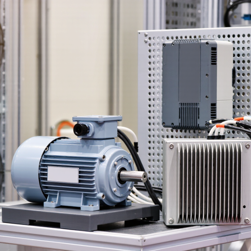
2026 How to Choose a Motor Braking Resistor?

Understand How a Motor Braking Resistor Controls Regenerative Energy

2026 How to Choose a Motor Braking Resistor?

Understand How a Motor Braking Resistor Controls Regenerative Energy

A braking resistor does not control regeneration; the drive’s braking chopper directs excess DC-bus energy into it. During deceleration, the motor acts as a generator, raising the DC-bus voltage. When that voltage reaches the drive’s threshold, the chopper switches on and sends current through the resistor. Electrical energy becomes heat. Heat is the trade-off.

The U.S. Department of Energy’s 2014 Improving Motor and Drive System Performance sourcebook estimates motor-driven systems use about 68% of U.S. industrial electricity. The IEA’s Energy Efficiency 2023 report puts industry’s share at roughly 37% of global energy consumption. These figures show the scale of motor energy use, not the savings a resistor can deliver. For selection, check resistance, peak braking power, pulse duration, and duty cycle against the drive manual and the actual load profile. A resistor that handles short stops may overheat during repeated cycles. Leave room for ventilation, and verify mounting temperature. I would question any sizing based only on motor power; deceleration time and load inertia matter too. A neat calculation can still miss a messy production cycle.

Gather the Motor and Drive Data Needed for Resistor Selection

Before choosing a braking resistor, collect the motor nameplate and drive data. Record rated power, voltage, current, base speed, and motor type. Note the drive’s DC-bus voltage, braking-transistor limits, and minimum permitted resistance. These limits matter: a resistor with too little resistance can overload the drive’s braking circuit.

Next, describe the actual load and motion. Capture load inertia, maximum speed, target stopping time, and stops per hour. Include overhauling loads, such as a descending lift, and any changes in product weight. Kinetic energy rises with the square of speed, so a small speed increase can sharply raise braking demand. The U.S. Department of Energy’s Improving Motor and Drive System Performance sourcebook reports that motor-driven systems use roughly 70% of industrial electricity. That system-level perspective is useful here: sizing from motor power alone misses the operating cycle.

Calculate energy per stop and average braking power, then check peak pulse power, resistor resistance, and cooling requirements against the drive and resistor specifications. Record ambient temperature, enclosure airflow, and mounting location; a resistor near a hot cabinet wall may shed less heat. Field measurements are imperfect. Note estimated inertia and uncertain cycle times rather than presenting them as exact values. Include the source and date of each measurement.

Calculate the Required Resistance and Braking Power

2026 How to Choose a Motor Braking Resistor?

Calculate the Required Resistance and Braking Power

Start with the drive’s braking-chopper voltage and current limits. The resistor must not fall below the drive’s specified minimum resistance. A useful check is R = V²/P, where V is the braking voltage and P is the required power. For example, at 700 V and 3,500 W, the calculated resistance is 140 ohms. Confirm that value against the drive manual; the chopper’s limits matter more than the arithmetic alone.

Estimate braking energy from the rotating system: E = ½Jω², using total inertia J and speed ω in radians per second. Include gravity-fed loads or other energy sources where applicable. Then estimate average braking power from the energy per stop and how often stops occur. A motor that stops a heavy load every few seconds needs a different resistor than one braking occasionally. Real cycles vary.

Check pulse-energy ratings, duty cycle, ambient temperature, and ventilation. A resistor may tolerate a brief high-power stop but overheat during repeated stops. Leave clearance around its hot surface, and use the specified enclosure and wiring. Test under the actual load while monitoring temperature and drive faults. I would not size from motor power alone; that shortcut misses inertia. It is easy to overlook. One imperfect input, such as an estimated load inertia, can shift the result, so verify assumptions before installation.

Check Duty Cycle, Thermal Limits, and Installation Conditions

2026 How to Choose a Motor Braking Resistor?

Check Duty Cycle, Thermal Limits, and Installation Conditions

A braking resistor needs to handle both the drive’s electrical limits and the machine’s stopping pattern. Check the drive documentation for its minimum resistance and braking current. Then estimate how often the motor stops, how long each braking event lasts, and how much energy it releases. A resistor that handles one stop may overheat during repeated cycles. Allow room.

Duty cycle matters. For example, a conveyor stopping every few seconds creates a different thermal load than a pump stopping occasionally. Compare the resistor’s continuous power rating with the average braking demand, and check its short-term energy rating for each stop. Leave a margin when operating conditions vary. Calculations help, but real loads can be less predictable than expected.

Installation affects temperature and service life. Mount the resistor on a stable, heat-resistant surface, following the specified clearances. Keep it away from cables, plastic parts, and other heat-sensitive components. A cramped enclosure can trap heat, even when the resistor’s rating seems adequate. Check airflow and ambient temperature, too. After commissioning, inspect temperatures during representative stops; one test cycle may not reveal the hottest operating condition.

2026 How to Choose a Motor Braking Resistor? — Check Duty Cycle, Thermal Limits, and Installation Conditions
Selection Dimension What to Check Engineering Guidance Practical Selection Check
Drive compatibility Whether the variable-frequency drive (VFD) has a built-in braking chopper or requires an external braking unit. A resistor must be connected to a compatible braking circuit. Follow the drive manual for terminals, wiring, protective devices, and supported resistor types. Confirm the drive model’s braking-resistor requirements before selecting a resistance or power rating.
Minimum resistance The drive’s specified minimum permissible resistance, in ohms (Ω). Resistance below the permitted minimum can cause excessive braking-chopper current and may damage the drive or braking unit. The permissible value is drive-specific. Choose a resistor whose rated resistance is at or above the drive’s stated minimum. Do not infer the limit from motor power alone.
Braking energy per stop Energy that must be dissipated during deceleration, in joules (J). For a rotating load, the change in kinetic energy is approximately ΔE = ½J(ω₁² − ω₂²), where J is the total inertia referred to the motor shaft in kg·m² and ω is angular speed in rad/s. Include load-driven energy and system losses as applicable. Use the actual load inertia, initial and final speeds, and stopping profile. A gravity-driven or overhauling load may add energy during braking.
Peak braking power Highest power during a braking event, in watts (W) or kilowatts (kW). Estimate event power from the energy and braking time, then check the peak against the resistor and braking unit’s permitted pulse-power limits. The power is not necessarily constant throughout deceleration. Verify both the resistor’s pulse rating and the braking unit’s current or power limits for the actual stopping profile.
Duty cycle and repetition Stops per hour, braking duration, and time between braking events. Average thermal loading depends on repeated events. A first estimate is average power = energy per event × events per second; use the manufacturer’s duty-cycle or pulse-energy data for final selection. Assess the most demanding normal operating sequence, including frequent starts and stops, not only a single emergency stop.
Continuous and average power Average heat dissipation over the operating cycle and the resistor’s continuous power rating. The continuous rating is valid only under the mounting, airflow, ambient-temperature, and enclosure conditions specified by the resistor manufacturer. Apply any required derating. Compare calculated average dissipation with the derated rating; do not treat a short-time peak rating as a continuous rating.
Thermal limits Resistor element, housing, terminal, and nearby equipment temperature limits. Braking resistors can become very hot in normal operation. Allow for ambient temperature, restricted airflow, enclosure temperature rise, and heat transfer to adjacent components. Check the datasheet’s temperature limits and clearance instructions. Keep combustible materials and temperature-sensitive components away from hot surfaces.
Installation location Ventilation, mounting orientation, vibration, dust, moisture, and enclosure protection. Install the resistor as specified by its manufacturer, with the required free space for cooling. An enclosure or protective cover can reduce airflow and may require derating. Confirm the intended mounting surface and environmental protection are suitable for the site; do not block ventilation openings.
Wiring and protection Conductor sizing, insulation temperature rating, routing, and any required thermal protection. Follow drive and resistor instructions for cable length, conductor size, grounding, overcurrent protection, and thermal-switch connection. Braking circuits can carry high current and generate electrical noise. Route braking-resistor wiring as specified by the drive manufacturer and provide the prescribed thermal cutout or alarm connection where required.
Resistance and voltage relationship Braking-circuit voltage and resistor current. For a chopper operating at a given DC-bus voltage, the approximate resistor current is I = V/R and instantaneous resistor power is P = V²/R. Actual chopper voltage and switching behavior are drive-specific. Use these relationships only as checks; select resistance and ratings using the drive’s published limits and braking-unit specifications.
Final verification Worst-case load, stopping time, repetition rate, ambient conditions, and drive fault limits. Validate the selection against the drive manual, resistor datasheet, and the machine’s complete operating cycle. Test temperatures and stopping performance during commissioning. Reassess if load inertia, speed, stopping time, cycle frequency, enclosure, or ambient temperature changes.

Verify Compatibility and Safety Before Commissioning

2026 How to Choose a Motor Braking Resistor?
Verify Compatibility and Safety Before Commissioning

Before energizing a drive, confirm the resistor’s resistance meets the drive’s specified minimum. Too little resistance can create excessive braking current; too much may fail to stop the load as required. Check peak power, pulse energy, and duty cycle against the actual stopping pattern—not motor kilowatts alone. A conveyor stopping every few seconds places a different thermal demand on a resistor than an occasional emergency stop. The U.S. Department of Energy’s 2014 Improving Motor and Drive System Performance sourcebook estimates that motor-driven systems use about 54% of U.S. manufacturing electricity. That scale makes careful drive-system selection and commissioning consequential.

Verify the DC-bus voltage range, wiring, protective devices, and the resistor’s thermal limits. Follow the drive manufacturer’s specified resistance and power ratings; then check that the enclosure allows heat to escape. IEC 61800-5-1:2022 addresses electrical, thermal, and fire hazards in adjustable-speed drive systems. Its safety framework is a useful reference, but it does not replace the drive’s installation instructions or a site-specific risk assessment. Small details matter. A resistor mounted beside a cable bundle can heat nearby insulation.

Tips: Measure resistance before connection, confirm the overtemperature switch works, and keep the resistor clear of combustible material. Record ambient temperature and braking frequency during testing. If readings differ from calculations, pause and investigate; a neat spreadsheet can still miss real operating conditions.

2026 How to Choose a Motor Braking Resistor? — Verify Compatibility and Safety Before Commissioning

Illustrative thermal example: For a 10 kW peak braking event, average dissipated power is calculated as peak power × duty cycle. The bars show 1, 2, 3, and 5 kW at 10%, 20%, 30%, and 50% duty cycle, respectively. These figures are an example, not a resistor specification. Before commissioning, verify the drive’s permitted resistance range, peak braking power and energy limits, resistor pulse and continuous ratings, wiring, cooling, and protective measures against the equipment manuals and application requirements.


Close

Raise your Query

Hi! Simply click below and type your query.

Our experts will reply you very soon.

WhatsApp Us
