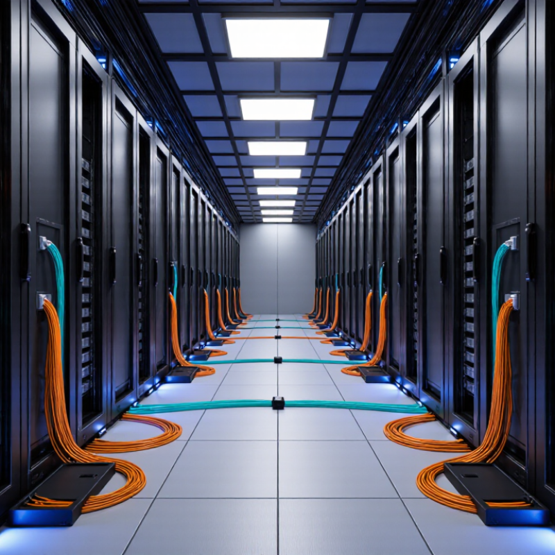
Data centers are expanding, but floor space rarely grows at the same pace as demand. More servers, faster links, and heavier east-west traffic put pressure on every rack and pathway. In this setting, High Density Fiber Optic Cable can carry more fiber connections through limited space. Picture a crowded cabinet: fewer bulky cable bundles can mean clearer routing and easier access to ports.
The International Energy Agency’s Electricity 2024 report says data-center electricity consumption could exceed 1,000 TWh by 2026. That forecast underlines the scale of digital infrastructure growth, though it does not measure fiber demand directly. Network pioneer Robert Metcalfe’s familiar principle states, “The value of a network is proportional to the square of the number of nodes in the network.” It is not a cable-design rule. Still, it helps explain why scalable connectivity matters as networks grow.
High Density Fiber Optic Cable may support cleaner pathways, higher port counts, and more flexible upgrades. Those benefits depend on the full design: connectors, bend radius, labeling, airflow, and technician access all matter. But density is not magic. A tightly packed panel can complicate maintenance if planning falls short. This guide examines where high-density fiber fits, what trade-offs to assess, and how data-center teams can judge whether it suits their environment. One detail deserves scrutiny: published capacity figures do not always reflect real installation conditions.
High-density fiber optic cable packs many optical fibers into a smaller cable diameter than conventional designs. The fibers may sit in compact tubes, ribbons, or flexible subunits, depending on the cable’s construction. Each fiber has a glass core surrounded by cladding. Light travels through the core, kept inside by reflection at the core-cladding boundary. Tiny pulses carry data. At the equipment end, transceivers convert electrical signals into light and back again.
In a data center, high fiber counts can connect server areas, switches, and patch panels while using less pathway space. Technicians often route trunk cables between cabinets, then use cassettes or panels to split the fibers into individual connections. That matters in practice. Less crowded trays can make future expansion easier, though dense bundles still need careful labeling and service access.
It is tempting to call higher density automatically better, but that misses the trade-off. Tighter cable layouts can make cleaning, tracing, and repairs more demanding. Small details matter. Installers must respect bend-radius limits, connector polarity, and airflow around equipment. A poorly planned high-count link can be harder to manage than a simpler one. The right design depends on fiber demand, available pathways, and how easily staff can maintain each connection.
In a data center, floor space is limited, but cable routes compete for room above racks, inside cabinets, and beneath raised floors. High-density fiber optic cable carries more fibers through a smaller pathway than many separate low-count cables. That can reduce tray congestion and leave more room for airflow, power leads, and technicians’ hands. The benefit is practical: fewer bundles to route and label. Still, a packed tray is not automatically a good design.
AFCOM’s 2024 State of the Data Center report puts average rack density at about 12 kW, up from 8.4 kW in 2020. Denser racks often need more network connections, making pathway space increasingly valuable. High-density trunks can connect rows through narrow overhead trays, while compact patch panels help conserve cabinet units. Leave room for bend-radius limits and future moves. Fiber is slim, but it can still be damaged by tight turns or careless handling.
Plan routes around access, not just maximum fiber count. Separate pathways where needed, label both ends, and keep service loops controlled. A technician should be able to trace one link without disturbing neighboring connections. This is where designs can fall short: installing the most fibers per tray may save space today, yet make repairs harder tomorrow. The right density depends on pathway capacity, cooling layout, and how often the network changes.
High-density fiber optic cable packs more strands into less pathway space, freeing room in trays and cabinets for additional links. That matters when a data hall adds rows of servers or connects more switches without expanding its footprint. Space matters. Synergy Research Group counted 1,136 operational hyperscale data centers worldwide at the end of 2024, reflecting the continuing scale of large facilities. More fiber capacity in existing pathways can make expansion easier to plan.
Performance depends on more than strand count. A high-density cable supports many parallel connections, but transceivers, connector quality, bend radius, and link design determine actual throughput and signal integrity. This distinction is easy to overlook. Teams should check insertion loss and polarity before deployment, especially when using multi-fiber connectors. A neat-looking trunk can still create troubleshooting headaches if labels or documentation are poor.
For scalability, modular trunk cables let technicians add connections in planned increments instead of pulling many individual fibers through busy routes. That can shorten installation work and reduce pathway congestion. Still, density is not magic. Tighter bundles can complicate access, and crowded cable paths may make future changes harder. Leave service loops, preserve bend limits, and document each connection. High-density fiber works best when capacity planning includes the people who will maintain it.
In a data center, high-density fiber optic cable helps connect many devices without filling every rack pathway. It is commonly used between switches in spine-leaf networks, where short, organized links support frequent traffic between servers. A compact trunk can carry multiple fiber channels from a network rack to nearby server rows. Less congestion. Technicians can trace routes more easily when cables are clearly labeled and arranged.
Cross-connect areas are another practical application. High-density trunks can link equipment rooms, meet-me spaces, and distribution frames across a facility. In colocation environments, this can make it easier to add customer connections without rebuilding entire cable routes. Large storage clusters and high-performance computing systems also use dense fiber links for high-throughput connections between switches and compute racks. The exact cable count and connector type should match the equipment and the planned upgrade path.
Deployment still needs care. Dense bundles can restrict airflow if they block rack openings, and tight bends may affect signal performance. Small details matter. Leave enough slack for service work, label both ends, and inspect connectors before installation. A crowded panel may look efficient on day one, yet become difficult to maintain later. That trade-off deserves attention during layout planning.
| Application or Scenario | Typical Cable and Fiber Count | Common Termination | Why High Density Helps | Deployment Considerations |
|---|---|---|---|---|
| Data center backbone links | Multifiber trunk cables commonly use 144, 288, or higher fiber counts, depending on pathway capacity and design. | Multifiber connectors or pre-terminated connectorized trunks; connector choice depends on the equipment and cabling architecture. | Consolidates many optical circuits into fewer cable runs and can reduce pathway congestion. | Plan fiber allocation, routing, labeling, bend radius, and spare capacity before installation. |
| Row-to-row and zone distribution | Trunk cables sized to the number of links serving the target rows or equipment zones. | Trunks connected to fiber enclosures, patch panels, or zone distribution points. | Creates an organized distribution layer while supporting multiple links in a shared pathway. | Keep routes accessible and separate cable management from power cabling as required by site standards. |
| Leaf-and-spine network connections | Multifiber trunks or parallel-fiber assemblies sized for the required switch links and port speeds. | Multifiber connectors for parallel optics, or duplex connectors where the transceiver interface requires them. | Supports a large number of switch-to-switch connections in a compact cabling footprint. | Match fiber type, polarity, connector configuration, and transceiver requirements at both ends. |
| High-speed parallel-optics links | Commonly uses multimode or single-mode multifiber cabling, selected to match the optical interface. | Multifiber connectors are often used for parallel-fiber interfaces. | Groups the transmit and receive fibers for a link into a compact, structured connection. | Verify the optical standard, reach, fiber type, polarity, and connector cleanliness before commissioning. |
| Equipment-row patching | High-fiber-count trunks feed local patching areas; shorter patch cords connect panels to equipment. | Panel-based cross-connects using connector types compatible with the installed trunk and devices. | Centralizes cable management and makes adds, moves, and changes easier to organize. | Use clear port labeling and preserve slack management without exceeding the cable's bend-radius limits. |
| Meet-me rooms and interconnection areas | High-count trunks connect distribution frames or panels across designated network areas. | Connectorized trunks or fusion-spliced termination, according to the operational design. | Provides a scalable way to route many fiber circuits through a limited number of pathways. | Coordinate pathway capacity, fire-stopping, access, and cable identification with facility requirements. |
| Existing-facility upgrades | Fiber count and cable diameter are selected after reviewing available ducts, trays, and growth needs. | Pre-terminated assemblies can reduce field termination work where compatible with the existing layout. | May add fiber capacity without requiring a separate cable run for every circuit. | Survey pathway fill, pulling tension, bend radius, connector access, and compatibility with existing fiber types. |
| New data center builds | Trunk capacity is designed around initial demand plus planned expansion and spare fibers. | Structured trunk-and-panel cabling or direct connections, depending on the architecture. | Enables repeatable installation and consistent cable routing across rows and zones. | Coordinate cable schedules, pathway layouts, labeling conventions, testing, and expansion plans. |
Fiber counts and connector arrangements vary by cable construction, equipment interface, and network design. Confirm the required fiber type, polarity, reach, and installation limits against the applicable equipment specifications and project standards.
Choosing high-density fiber cable starts with the rack, not the catalog. Measure available panel space and count the connections each cabinet actually needs. A 144-fiber trunk may reduce cable bulk, but only if its connectors match the equipment and patching plan. Check connector type, fiber mode, strand count, and polarity before ordering.
Bend radius matters. Tight turns behind a drawer can damage performance or make servicing difficult. Compare cable diameter and minimum bend radius with the route from tray to panel. Then check insertion-loss limits against the link budget, especially when several connectors or splices sit in one path. Test sample assemblies when specifications leave room for interpretation. There is a trade-off.
Plan for airflow and access, too. Dense bundles can obstruct vents or hide labels, making a simple fault harder to trace. Leave room for routing slack, clear port identification, and safe connector cleaning. Planning documents rarely show every awkward patch-cord crossing. A practical review with installers can reveal these snags before the rack is full. A little spare capacity helps, but excess cable can crowd the same space you hoped to save.
Common MPO connector formats can carry multiple fibers in a single connector, helping increase connection density in rack and patch-panel environments.
What to consider: Fiber count is only one factor. Check connector compatibility, polarity, insertion-loss limits, bend radius, cable routing space, cleaning access, and future expansion needs. Higher fiber count does not by itself guarantee better network performance.
Hi! Simply click below and type your query.
Our experts will reply you very soon.
