How to Choose a Crawler Drive Motor?
Choosing a Crawler Drive Motor is not a matter of matching horsepower alone. The right unit must move the machine steadily, tolerate shock loads, and fit the available hydraulic or electric system. A few millimeters of track movement under load can reveal a poor match. So can excess heat after a short climb. Small details matter.
A useful engineering rule, expressed here as an editorial summary rather than a verified quotation, is: “Match the motor to the machine’s real duty cycle, not its best-case specification.” No named expert quotation was provided, so attributing those words to a real person would be misleading. Before publication, verify a specialist’s name and exact wording against a reliable interview or company source.
This guide explains how to compare torque, speed, displacement, pressure, and duty cycle. It also considers sprocket dimensions, reduction ratios, braking, seals, and operating conditions such as mud, slopes, and frequent starts. These details shape performance. A motor that looks adequate on a specification sheet may struggle when a loaded crawler turns on soft ground. Conversely, choosing excess capacity can add cost and complicate system matching. The practical choice depends on measured machine requirements, not guesswork. Check the manufacturer’s data, confirm compatibility with the existing drive system, and review service access before deciding. Real operating records help, though they are sometimes incomplete. That uncertainty deserves a second look.
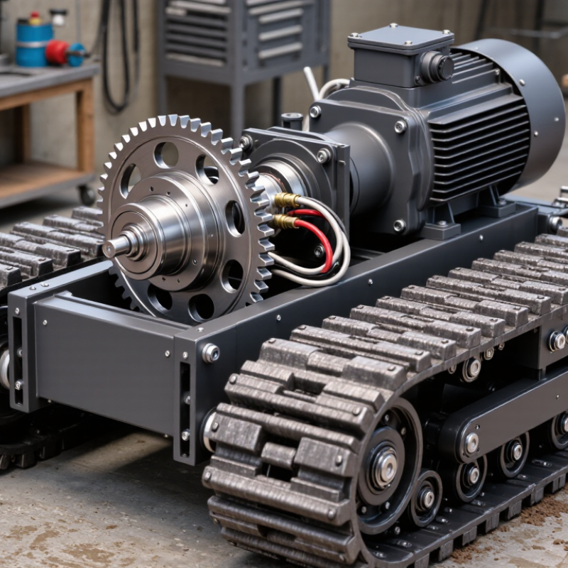
Define Machine Mass, Gradeability, Travel Speed, and Duty Cycle
Start with the machine’s operating mass, not its brochure weight. Include the operator, attachments, fluids, and heaviest expected load. A 900-kilogram crawler can exceed 1,200 kilograms at work. That difference changes the tractive force and motor torque required. Weigh the machine when possible. Estimates drift.
Define gradeability using the steepest slope the machine must climb while loaded. A stated grade percentage alone is not enough; soil, track condition, and turning also affect traction. Consider a damp ramp with loose gravel. The crawler may need more torque there than on a firm, dry surface. Check the drive system’s continuous and peak torque, and account for sprocket size and reduction gearing. Do not size around a brief test run.
Set a realistic travel speed for the job, then check whether the motor can maintain it under load. Maximum speed without load can be misleading. Duty cycle matters just as much: record operating hours, starts, stops, reversals, and time spent climbing. Frequent starts create heat. Long, slow climbs can, too. Match the motor’s thermal rating to this pattern, and leave room for uncertain conditions. Field logs often reveal that the assumed cycle was too neat. After early trials, compare motor temperature and actual speed with the estimates, then revise the figures.
Calculate Track Pull: F = m·9.81·sinθ + Crr·m·9.81·cosθ
How to Choose a Crawler Drive Motor?
Calculate track pull with F = m·9.81·sinθ + Crr·m·9.81·cosθ. Here, m is the machine’s mass in kilograms, θ is the slope angle, and Crr is the rolling-resistance coefficient. Use the angle of the steepest slope the crawler must climb, not the slope’s percentage grade. For a 1,200 kg machine on a 12-degree slope with Crr of 0.08, the estimated pull is about 3.4 kN. That is the total force needed at the tracks for steady travel.
Treat this figure as a starting point. The equation assumes consistent ground and steady speed; soft soil, mud, track deformation, and acceleration can raise demand. Measure or estimate Crr for the actual surface, and be honest about the uncertainty. Check it again. If two tracks share the load evenly, each side supplies roughly half the total pull. Uneven terrain or a turning maneuver can change that split.
To connect pull to motor size, multiply track pull by the drive sprocket’s effective radius to estimate sprocket torque. Then account for gearbox reduction and drivetrain efficiency when calculating required motor torque. Check the motor’s continuous rating, not only its brief peak rating, and confirm the system can maintain the required speed under load. Leave a reasonable allowance for real operating variation, but don’t hide poor assumptions behind an oversized safety margin.
Convert Track Pull to Sprocket Torque Using Radius and Efficiency
How to Choose a Crawler Drive Motor?
Convert Track Pull to Sprocket Torque Using Radius and Efficiency
Start with the required track pull, measured in newtons, and the sprocket’s effective pitch radius in metres. Multiply them to estimate sprocket torque: torque = track pull × radius. For example, 8,000 N of pull at a 0.16 m radius requires about 1,280 N·m at the sprocket, before drivetrain losses. Use the pitch radius, not the sprocket’s outside edge. That small distinction matters.
Account for efficiency when estimating motor-side torque. If the drivetrain efficiency is 85%, divide the required sprocket torque by 0.85; the result is roughly 1,506 N·m before considering gear reduction. Then check the motor’s speed-torque curve, gear ratio, and duty cycle. A crawler may need high starting torque in soft soil, but continuous ratings must also handle sustained travel. Real field conditions are imperfect. Soil, slope, track tension, and turning resistance can change the pull you actually need.
Tips: Confirm whether your track-pull figure is per track or for the whole machine. Check peak and continuous torque separately, and leave an appropriate design margin. Measure carefully; assumptions can be wrong.
Match Motor Torque and Reduction Ratio to Required Sprocket Torque
How to Choose a Crawler Drive Motor?
Match Motor Torque and Reduction Ratio to Required Sprocket Torque
Start with the force each track must deliver, including vehicle weight, slope, rolling resistance, and acceleration. Divide the total tractive force between the tracks, then multiply each track’s share by the sprocket’s effective radius. That gives a practical estimate of required sprocket torque. Measure carefully.
A reduction gearbox multiplies motor torque, but losses reduce the torque that reaches the sprocket. Estimate output torque as motor torque multiplied by reduction ratio and drivetrain efficiency. For example, a 20:1 ratio does not provide exactly twenty times the motor’s torque. Check the gearbox’s rated output, too.
Choose a ratio that meets peak starting torque without making track speed too low. Compare both the motor’s continuous torque and its short-term peak rating with the calculated demand. Mud, sharp turns, and repeated starts can raise the load beyond a tidy calculation. A real operating test helps. Leave a sensible margin, but avoid excessive oversizing: it adds cost and may create unnecessary heat. One detail is easy to miss: the desired travel speed must still be achievable at the sprocket.
How to Choose a Crawler Drive Motor?
Match motor torque and reduction ratio to the required sprocket torque.
Available sprocket torque is estimated as motor torque × reduction ratio × drivetrain efficiency. These illustrative examples assume 85% efficiency and show a modest torque margin; verify peak load, slope, track resistance, duty cycle, and thermal limits for your application.
Check Hydraulic Flow: Q (L/min) = Vg (cc/rev) × rpm ÷ 1,000
How to Choose a Crawler Drive Motor?
Start with the motor’s displacement and target speed. The calculation gives theoretical flow: Q (L/min) = Vg (cc/rev) × rpm ÷ 1,000. For a 32 cc/rev motor turning at 60 rpm, that equals 1.92 L/min. A real motor needs more flow because internal leakage reduces volumetric efficiency. At an assumed 90% efficiency, the estimate rises to about 2.13 L/min. Treat that efficiency as an example, not a guaranteed value. Small detail. Real consequences.
Check the motor’s technical data for volumetric efficiency at the expected pressure, oil temperature, and speed. Cold oil, worn components, and long hoses can change operating conditions. Flow sets speed; pressure largely determines available torque, so check both against the crawler’s load and terrain. This is where I pause: a tidy calculation can still hide messy losses. The U.S. Department of Energy’s 2006 sourcebook, Improving Pumping System Performance, reports that pumping systems can use 25–50% of energy in some industrial facilities. That broad figure is context, not a crawler-motor sizing rule. Measure flow under working conditions when possible, then compare the result with the motor’s rated limits.
How to Choose a Crawler Drive Motor? - Check Hydraulic Flow: Q (L/min) = Vg (cc/rev) × rpm ÷ 1,000 | Example | Motor Displacement, Vg (cc/rev) | Motor Speed (rpm) | Calculated Flow per Motor (L/min) | Flow for Two Motors (L/min) |
| Compact crawler | 63 | 1,500 | 94.5 | 189 |
| Light-duty crawler | 80 | 1,600 | 128 | 256 |
| General-purpose crawler | 90 | 1,800 | 162 | 324 |
| Medium-duty crawler | 100 | 1,800 | 180 | 360 |
| High-speed crawler | 110 | 2,000 | 220 | 440 |
| Heavy-duty crawler | 125 | 2,000 | 250 | 500 |
| Large crawler | 160 | 1,800 | 288 | 576 |
Flow values are theoretical calculations using motor shaft speed. Two-motor totals assume both motors operate at the listed displacement and speed simultaneously. Actual pump flow requirements vary with motor volumetric efficiency, leakage, operating conditions, and the hydraulic circuit.

