7 Tips for Choosing Optical Cable Adapters

Optical Cable Adapters look small, yet they influence alignment, signal loss, and maintenance time across a fiber network. A poorly matched adapter can create reflection, loosen under vibration, or complicate future upgrades. These details matter more as networks become denser.

Cisco’s Annual Internet Report (2018–2023) projected 5.3 billion internet users and 29.3 billion networked devices by 2023. That scale places greater pressure on stable fiber connections. The ITU’s Facts and Figures 2023 reported that 67% of the world’s population used the internet. More connected endpoints mean more interfaces to inspect.

Small parts. Large consequences.

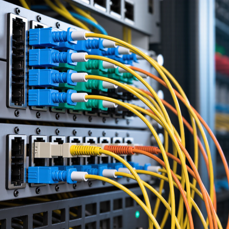
Choosing the right Optical Cable Adapters requires more than checking connector shape. Technicians should assess fiber mode, polish type, insertion loss, return loss, housing material, and environmental ratings. The adapter must also fit the panel, rack, or splice enclosure precisely. A blue SC/UPC adapter is not automatically suitable for a green SC/APC connection. Color can guide inspection, but specifications must decide.

This guide presents seven practical selection tips based on field experience, manufacturer specifications, and recognized industry data. It considers single-mode and multimode systems, common LC and SC formats, and demanding data-center conditions. No checklist is perfect. Real installations may expose overlooked dust, bend stress, or inconsistent labeling. That is why testing with calibrated equipment remains essential. Careful selection reduces rework, protects optical performance, and supports dependable network growth.
7 Tips for Choosing Optical Cable Adapters

Understanding Optical Cable Adapter Types and Their Applications

Choosing an optical cable adapter starts with identifying the connector family and network environment. Common types include LC, SC, ST, and multi-fiber push-on adapters. LC adapters suit dense panels because their bodies are compact. SC adapters offer a larger push-pull housing, which helps technicians wearing gloves. ST adapters remain useful in older industrial and building systems.

Check the fiber mode before checking price. Single-mode adapters support long-distance links, while multimode adapters serve shorter data-center connections. Duplex adapters carry two fibers in one housing. Simplex versions carry one. For rack installations, choose keyed adapters, protective shutters, and accurate panel cutouts. A poor fit can increase insertion loss, even when the cable looks perfect. I have seen this overlooked.

Application details matter. Fiber-to-the-home networks often need sealed, durable adapter assemblies. Data centers usually prioritize density, polarity control, and quick maintenance. Industrial sites may require stronger retention and better dust protection. The ITU’s Facts and Figures 2023 reported 5.4 billion people online, showing why scalable connectivity infrastructure matters. The Cisco Annual Internet Report forecast 29.3 billion networked devices by 2023. Those figures do not measure adapters directly, but they explain rising pressure on fiber distribution systems. Before ordering, compare connector geometry, polish type, fiber mode, alignment sleeves, and operating temperature. Leave room for human error. Even experienced installers sometimes choose compatibility by appearance alone.

7 Tips for Choosing Optical Cable Adapters: Types and Applications

Typical maximum insertion-loss values commonly specified for standard single-mode and multimode fiber adapters are shown below. Lower loss indicates better optical coupling performance.

How to choose: Match the adapter to the connector type, fiber mode, polarity, mounting style, and required optical performance. LC adapters are common in high-density data-center panels, SC adapters are widely used in telecom and FTTH systems, ST and FC adapters suit legacy or specialized installations, and MPO adapters support high-density parallel-fiber connections.

Matching Adapter Compatibility with Fiber Connectors and Cable Standards

7 Tips for Choosing Optical Cable Adapters

Matching an adapter starts with identifying the fiber connector, not the equipment label. Check whether the system uses LC, SC, ST, or MPO-style connectors. Confirm the connector polish, such as UPC or APC. Never mate different polish types. They may fit physically, but reflections can damage performance. Verify single-mode or multimode fiber before ordering. An adapter cannot convert one fiber category into another.

Review the cable standard next. OS1 and OS2 serve single-mode links, while OM3, OM4, and OM5 support multimode networks. The IEC 61754 family defines connector interfaces, while IEC 61755 addresses optical interface performance. For difficult routing, ITU-T G.657 guidance helps assess bend-insensitive fiber compatibility. Check keying, gender, alignment sleeves, mounting style, and panel depth. Small mechanical errors become visible as unstable links. The OECD’s 2024 Broadband Statistics reported fiber at roughly 42% of fixed broadband subscriptions, increasing the need for consistent connector practices.

Ask for insertion-loss and return-loss specifications, not only a low price. Measure a sample link with a light source and power meter. I once trusted a matching connector shape and missed a polished-end mismatch. The link passed briefly, then failed under movement. That mistake changed my checklist. Confirm adapter material, temperature range, cleaning requirements, and replacement availability. Keep a record of connector type, fiber class, polarity, and test results. Standards reduce uncertainty, but field conditions still matter.

Checking Insertion Loss, Return Loss, and Signal Performance

7 Tips for Choosing Optical Cable Adapters

A suitable optical cable adapter must protect signal quality, not merely match connector shapes. The Fiber Optic Association reports that a well-made mated connection often shows about 0.2 dB insertion loss. Poor alignment, dust, or damaged end faces can push loss toward 0.5 dB or higher. Measure at 1310 nm and 1550 nm when possible. Real networks may behave differently than factory labels suggest.

Tip 1: Check insertion loss with an optical loss test set, not visual inspection alone. IEC 61300-3-34 defines a method for measuring connector attenuation. Tip 2: Review return loss carefully. Common field targets are at least 50 dB for UPC connections and 60 dB for APC connections, but the actual requirement depends on the equipment and transmission system. Lower return loss means stronger reflections. That can disturb sensitive transmitters.

Tip 3: Confirm adapter geometry, sleeve material, and alignment tolerance. Ceramic sleeves usually provide stable centering, while worn sleeves can create fluctuating readings. Tip 4: Clean, inspect, and reclean both end faces before testing. One tiny particle can produce a surprising fault. Tip 5: Compare results with the system budget, including every splice and connector. A technician may blame the adapter too quickly; a bent cable or unstable test reference can cause the same symptom. TIA-568.3-E guidance and manufacturer test records should support the final selection, though field conditions often expose gaps in laboratory assumptions.

7 Tips for Choosing Optical Cable Adapters - Checking Insertion Loss, Return Loss, and Signal Performance

Tip What to Check Practical Selection Guide Why It Matters
1. Match the fiber type Confirm whether the link uses single-mode or multimode fiber, and check the adapter and connected cables are compatible. Use single-mode components with single-mode fiber and multimode components with the appropriate multimode fiber type. Check the system’s operating wavelengths, commonly 1310/1550 nm for single-mode and 850/1300 nm for multimode. Fiber mismatch can increase loss and impair signal performance, even when the connectors appear to fit.
2. Check connector and polish compatibility Match the connector format, such as LC, SC, or ST, and the end-face polish, such as UPC or APC. Mate UPC with UPC and APC with APC. APC connectors are commonly identified by an angled end face and often a green housing; color conventions can vary, so verify the product specification. Incompatible connector formats may not mate correctly. Mixing APC and UPC can cause poor contact, higher loss, and reflections.
3. Set a suitable insertion-loss target Review the maximum insertion loss (IL) for the mated connector pair and the test conditions used to measure it. As a practical procurement example, specify a maximum of 0.3 dB per mated pair for general applications; consider 0.2 dB or lower where the link budget is tight. Confirm requirements for the intended fiber type and wavelength. Lower insertion loss leaves more optical power available to overcome cable, splice, and other connection losses.
4. Verify return loss for the application Check the return-loss (RL) requirement for the complete mated connection, including both connector end faces. Typical single-mode targets may be at least 50 dB for UPC and at least 60 dB for APC, but values vary by specification and application. Use the system requirement rather than treating these figures as universal limits. Higher return loss means less reflected optical power. This is especially important for reflection-sensitive transmitters and some high-performance links.
5. Inspect cleanliness and end-face condition Check both connector end faces for dust, oil, scratches, chips, and other contamination before mating. Inspect with an appropriate fiber inspection scope and clean with materials designed for fiber connectors. Reinspect after cleaning and before connection. Contamination can cause excess loss, reflections, or permanent end-face damage. An adapter does not compensate for a dirty connector.
6. Assess alignment and repeatability Review the adapter’s alignment-sleeve material, mechanical fit, and performance across repeated mating cycles. Choose a sleeve and connector interface specified for the intended connector format. Where repeatability matters, request test data for insertion loss after repeated connections. Accurate alignment helps maintain consistent optical coupling and reduces variation when connections are disconnected and remated.
7. Confirm measurement and environmental requirements Check test method, wavelength, reference procedure, operating temperature, and any dust or moisture protection needed at the installation site. Request IL and RL results for the relevant configuration. IEC 61300-3-4 and IEC 61300-3-6 describe measurement methods for attenuation and return loss, respectively; confirm the applicable test setup with the supplier. Results are meaningful only when the measurement conditions match the application. Environmental suitability helps preserve performance in the installed location.

Note: Insertion-loss and return-loss figures are example selection targets, not guarantees for every adapter or application. Confirm the required limits, test configuration, and compatibility with the complete optical link specification.

Evaluating Materials, Durability, and Installation Environment

7 Tips for Choosing Optical Cable Adapters

Evaluating Materials, Durability, and Installation Environment

Material choice affects alignment, signal stability, and service life. Ceramic ferrules usually provide accurate core alignment and consistent connection performance. Metal housings resist impact, while polymer bodies reduce weight and installation strain. Match the adapter material with the cable connector and expected handling conditions. Do not assume a cheaper body is unreliable. Check its tolerances, surface finish, and documented insertion loss.

Durability depends on more than housing strength. Inspect latch quality, sleeve alignment, dust protection, and resistance to repeated mating. In a busy cabinet, loose adapters can suffer vibration and accidental pulls. Choose a design with clear polarity and firm retention.

My first choice was not perfect. I once underestimated cable bend pressure, and the connection became unstable after maintenance work. That mistake changed my inspection routine.

The installation environment deserves equal attention. Outdoor routes may expose adapters to moisture, ultraviolet light, temperature changes, and insects. Indoor data rooms may create different risks, including dust, crowding, and poor airflow. Select sealing and temperature ratings that match the actual site, not an ideal laboratory. Leave enough space for cleaning and testing. Confirm compatibility with applicable connector standards. Before deployment, measure insertion loss and return loss with calibrated equipment. Test again after routing. Small movements matter. Keep protective caps fitted until final connection, and record any unusual fit or resistance for later review.

Comparing Quality, Certifications, Cost, and Long-Term Support

7 Tips for Choosing Optical Cable Adapters

Compare adapters by interface, materials, and test evidence—not appearance alone. ITU’s Facts and Figures 2023 estimated that 5.4 billion people were online, underscoring the scale of networks that depend on reliable links. That figure does not predict adapter failure rates, but it highlights why small connection losses matter. Check that the adapter matches the connector type and fiber mode. IEC 61754 standards define fiber-optic connector interfaces; ask suppliers for documented conformity, not just a printed “compliant” label. A polished label is not proof. Inspect the ceramic alignment sleeve and housing for cracks, burrs, or loose fit. Request insertion-loss and return-loss test results, and compare them against your project’s limits.

Cost should include more than the unit price. Include cleaning tools, replacement stock, testing time, and expected downtime. Check whether the supplier provides traceable test records, clear warranty terms, and technical help after purchase. Confirm that replacement adapters will remain compatible with installed panels and patch cords. ITU’s data describes broad connectivity, not the lifetime of any component; use site-specific test records for that. During installation, inspect end faces and measure the link after mating. Small dust particles can disrupt performance. Even careful teams miss things. Record the adapter type, test result, and installation date; these details make later troubleshooting faster, though recordkeeping alone cannot prevent a poor connection.


Close

Raise your Query

Hi! Simply click below and type your query.

Our experts will reply you very soon.

WhatsApp Us
